Connection Diagram Of Ammeter. The following circuit represents the basic circuit diagram and the connection of the ammeter circuit in series and parallel are shown below. It is an important tool for electricians and engineers to monitor and troubleshoot electrical systems. the wiring diagram for an ammeter typically includes the following components: The ammeter is connected in series with the circuit, allowing the current to flow through it and measure its magnitude. an ammeter is an instrument used to measure the current flowing in a circuit. By finding a current’s amperage, you can diagnose underperforming electrical circuits. in the below diagram, i have shown how to wire an amp meter, in the diagram i have shown two wire coolers of which one is black and the second is. A power source, a shunt, a wiring harness, and the ammeter itself. To properly connect an ammeter, a wiring diagram is necessary to understand the circuit and the components involved. the ammeter wiring schematic consists of several components, including the ammeter itself, shunt resistor, and power source. to properly use an ammeter, it is crucial to understand its connection diagram and how to connect it to the circuit. An ammeter is defined as a device that measures the electric current in a circuit. ammeter circuit diagram the construction of ammeter can be done in two ways like series and shunt. ammeters measure the strength of a current flowing through an electrical circuit in amperes (a).
from schematicmanualalan.z13.web.core.windows.net
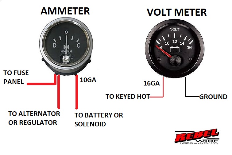
the wiring diagram for an ammeter typically includes the following components: By finding a current’s amperage, you can diagnose underperforming electrical circuits. in the below diagram, i have shown how to wire an amp meter, in the diagram i have shown two wire coolers of which one is black and the second is. ammeters measure the strength of a current flowing through an electrical circuit in amperes (a). A power source, a shunt, a wiring harness, and the ammeter itself. to properly use an ammeter, it is crucial to understand its connection diagram and how to connect it to the circuit. It is an important tool for electricians and engineers to monitor and troubleshoot electrical systems. An ammeter is defined as a device that measures the electric current in a circuit. ammeter circuit diagram the construction of ammeter can be done in two ways like series and shunt. To properly connect an ammeter, a wiring diagram is necessary to understand the circuit and the components involved.
Automotive Ammeter Wiring Diagram
Connection Diagram Of Ammeter By finding a current’s amperage, you can diagnose underperforming electrical circuits. an ammeter is an instrument used to measure the current flowing in a circuit. The ammeter is connected in series with the circuit, allowing the current to flow through it and measure its magnitude. ammeters measure the strength of a current flowing through an electrical circuit in amperes (a). ammeter circuit diagram the construction of ammeter can be done in two ways like series and shunt. in the below diagram, i have shown how to wire an amp meter, in the diagram i have shown two wire coolers of which one is black and the second is. to properly use an ammeter, it is crucial to understand its connection diagram and how to connect it to the circuit. the wiring diagram for an ammeter typically includes the following components: An ammeter is defined as a device that measures the electric current in a circuit. It is an important tool for electricians and engineers to monitor and troubleshoot electrical systems. A power source, a shunt, a wiring harness, and the ammeter itself. To properly connect an ammeter, a wiring diagram is necessary to understand the circuit and the components involved. the ammeter wiring schematic consists of several components, including the ammeter itself, shunt resistor, and power source. The following circuit represents the basic circuit diagram and the connection of the ammeter circuit in series and parallel are shown below. By finding a current’s amperage, you can diagnose underperforming electrical circuits.